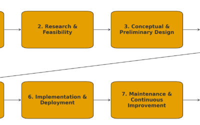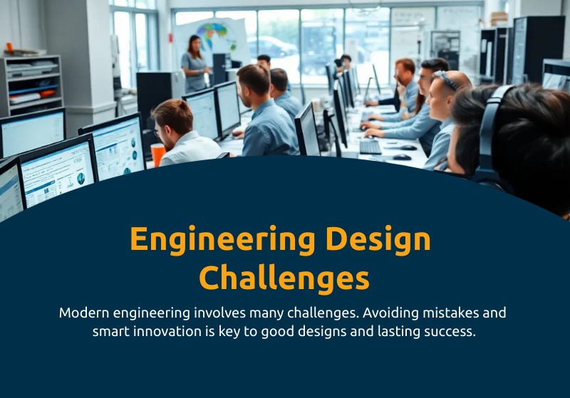
The Complexity of Modern Engineering Design
Designing engineering systems is as much about avoiding mistakes as it is about innovation. Every decision — whether it’s choosing a material, configuring a control system, or running a thermal simulation — has consequences for cost, reliability, and long-term performance.
The engineering community often rallies around shared questions:
- How do I design for power systems, fluid flow, or thermal management?
- Which material is best for this application, and how do I avoid failure modes?
- What challenges should I anticipate during prototyping or manufacturing?
- How do I validate my design with CAD, simulation, or finite element analysis (FEA)?
- What’s the right way to configure sensors, instrumentation, and control systems?
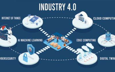
- How do I integrate software architecture into embedded or IoT contexts?
These aren’t abstract questions — they reflect the core work of engineers. Get them wrong, and projects collapse under budget overruns, field failures, or safety issues. Get them right, and organizations unlock performance gains, regulatory compliance, and customer trust.
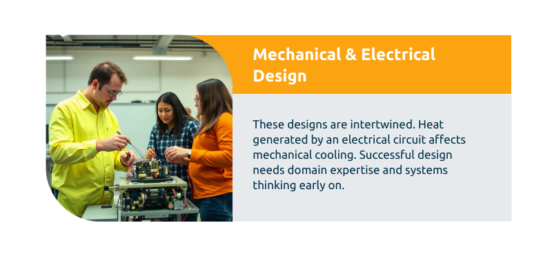
Designing for Mechanical and Electrical Systems
The Balancing Act
Mechanical and electrical design decisions are intertwined. For instance, the heat generated by an electrical circuit directly affects the choice of mechanical cooling methods. Successful design requires both domain expertise and systems thinking.
Power Systems
- Load Analysis: Engineers must calculate peak, average, and fault loads to size transformers, circuit breakers, and conductors.
- Redundancy: Mission-critical systems require backup capacity and fault-tolerant architecture.
- Efficiency Trade-offs: High-efficiency components reduce operating costs but may increase upfront capital costs.
Fluid Flow Systems
- Flow Regimes: Laminar vs. turbulent flow drastically changes pump sizing and pressure drop calculations.
- Pressure Loss Estimation: Friction factors, bends, and fittings add cumulative resistance that must be modeled accurately.
- Safety Margins: Piping and vessels must account for surges, transients, and possible cavitation.
Thermal Management
- Conduction, Convection, Radiation: Engineers must evaluate all three modes for accurate heat dissipation design.
- Passive vs. Active Cooling: Heat sinks and natural convection work for smaller systems; fans, liquid cooling, or phase-change solutions may be required for high loads.
- Integration with Electronics: Thermal considerations should be addressed at the PCB and enclosure level, not as an afterthought.
Key Takeaway: The best designs emerge when mechanical and electrical engineers collaborate early, ensuring system-level optimization rather than patchwork fixes.

Material Selection and Failure Modes
Why Materials Matter
Material choice is often the single most important factor in determining whether a design will succeed in real-world conditions. The wrong material can lead to catastrophic failures, warranty claims, and reputational damage.
Selection Criteria
- Mechanical Properties: Yield strength, hardness, toughness, fatigue resistance.
- Environmental Resistance: Corrosion, UV exposure, thermal expansion.
- Manufacturability: Machinability, weldability, availability.
- Cost & Sustainability: Lifecycle costs, recyclability, and regulatory compliance.
Common Failure Modes
- Fatigue: Repeated cyclic loading causes cracks to propagate.
- Creep: Materials deform permanently under sustained stress at high temperature.
- Corrosion: Electrochemical degradation weakens metals over time.
- Thermal Shock: Sudden temperature changes induce cracking.
- Wear: Surface degradation reduces functional lifespan.
Tools for Decision-Making
- Ashby Charts: Visualize trade-offs between properties.
- Finite Element Analysis (FEA): Model stress concentrations to anticipate fatigue or failure.
- Accelerated Life Testing (ALT): Simulate real-world conditions to validate durability.
Key Takeaway: Material selection is never just about strength — it’s about matching properties to real operating environments while balancing cost and manufacturability.

Manufacturing and Prototyping Issues
From CAD to Reality
Even the most elegant design can stumble when it reaches the factory floor. Manufacturing constraints must be built into the design phase to avoid costly rework.
Common Issues
- Tolerances & Fits: Overly tight tolerances drive up machining costs unnecessarily.
- DFM (Design for Manufacturability): Simplify parts to reduce machining time, assembly errors, and tooling expenses.
- DFAM (Design for Additive Manufacturing): Optimize geometries for 3D printing — lightweight structures, reduced material waste, and faster prototyping.
- Material Availability: Exotic alloys may be theoretically perfect but practically impossible to source.
Prototyping Challenges
- Rapid Iteration: 3D printing and CNC machining allow fast cycles but may not reflect final production constraints.
- Scale-Up Risks: A prototype that works at small scale may fail during mass production due to thermal expansion, stress concentrations, or assembly complexity.
- Supplier Alignment: Early engagement with suppliers prevents surprises in tooling, lead times, and quality standards.
Key Takeaway: Manufacturing success depends on anticipating constraints early and designing with the factory — not just the lab — in mind.

CAD, Simulation, and Finite Element Analysis (FEA)
CAD as the Design Foundation
Computer-Aided Design (CAD) tools are the backbone of modern engineering workflows. They don’t just generate 3D models — they define how every other process, from prototyping to simulation to manufacturing, unfolds.
Best Practices for CAD Design:
- Parametric Modeling: Build parts with constraints and relationships, enabling quick updates without redrawing.
- Standard Libraries: Use verified component libraries to reduce errors and accelerate design.
- File Management: Poor version control in CAD can create inconsistencies downstream. Cloud-based PDM (Product Data Management) systems mitigate this.
Simulation for Decision-Making
Simulation allows engineers to test “what-if” scenarios without the cost of physical prototypes.
- CFD (Computational Fluid Dynamics): Model airflow, liquid cooling, or combustion efficiency.
- Thermal Simulations: Predict hotspots and validate cooling strategies.
- Electromagnetic Analysis: Ensure compliance in high-frequency or IoT applications.
Finite Element Analysis (FEA)
FEA breaks down complex geometries into discrete elements, allowing stress, strain, and deformation analysis.
Applications:
- Predicting fatigue life in aerospace structures.
- Optimizing automotive crashworthiness.
- Verifying mechanical safety in medical devices.
Common Pitfalls:
- Over-Simplification: Ignoring small features that become failure points.
- Mesh Quality Issues: Coarse meshes reduce accuracy, while excessively fine meshes waste computing power.
- Boundary Condition Errors: Unrealistic assumptions lead to misleading results.
Key Takeaway: CAD and FEA are only as valuable as the engineer’s assumptions. Human judgment is critical in interpreting results and translating them into actionable design improvements.
Control Systems, Sensors, and Instrumentation
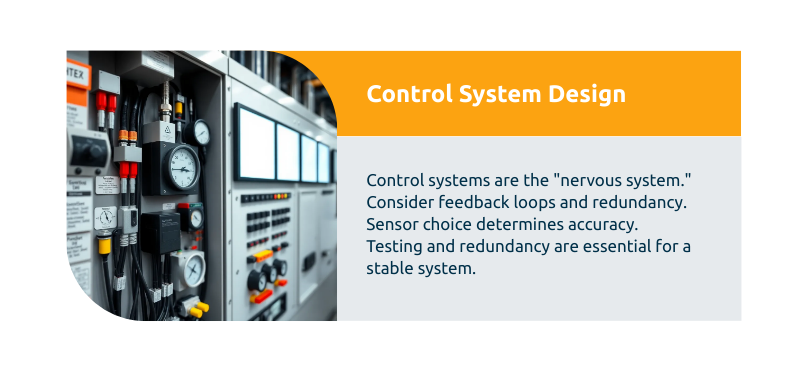
Control Systems as the “Nervous System” of Engineering Projects
From industrial automation to medical devices, control systems provide the decision-making logic that governs performance.
Core Design Considerations:
- Feedback Loops: Proportional-Integral-Derivative (PID) controllers remain industry workhorses. Poorly tuned loops lead to instability.
- Redundancy: Safety-critical systems (aerospace, nuclear, healthcare) require redundant control pathways.
- Latency: Even millisecond delays in feedback can destabilize dynamic systems.
Sensors and Instrumentation
Sensors are the “eyes and ears” of any control system, and choosing the right instrumentation determines accuracy and reliability.
- Selection Criteria: Accuracy, response time, environmental resistance, calibration requirements.
- Integration Issues: Signal noise, power requirements, and interface compatibility.
- IoT Implications: Wireless sensors improve flexibility but introduce cybersecurity vulnerabilities.
Example: In automotive applications, improperly calibrated pressure sensors can trigger false alarms or, worse, fail to detect critical conditions like brake system leaks.
Key Takeaway: The weakest link in control systems often isn’t the logic — it’s the sensor configuration and integration. Rigorous testing and redundancy are essential.
Software Architecture and System Integration in Embedded or IoT Contexts
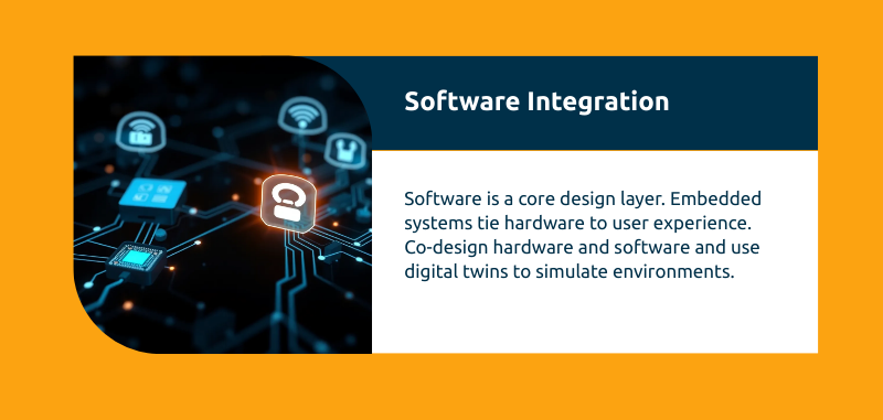
Why Software Matters in Hardware-Centric Fields
Even in traditional mechanical and electrical projects, software is no longer an add-on — it’s a core design layer. Embedded systems and IoT architectures tie hardware performance to user experience, scalability, and security.
Core Elements of Software-Embedded Design
- Real-Time Operating Systems (RTOS): Critical for robotics, aerospace, and medical devices where timing precision matters.
- Modular Architecture: Break down functions into reusable code modules for flexibility and easier debugging.
- Cybersecurity: Connected devices must account for encryption, access control, and update management from day one.
Integration Challenges
- Hardware-Software Mismatch: Poor alignment between hardware capabilities and software requirements creates bottlenecks.
- Scalability: Prototypes may work with a few devices but collapse when thousands of IoT nodes are deployed.
- Interoperability: Devices must communicate reliably across diverse protocols (Bluetooth, Wi-Fi, Zigbee, LoRa).
Best Practices:
- Co-design hardware and software from the start.
- Use digital twins to simulate large-scale IoT environments.
- Implement over-the-air (OTA) updates to extend lifecycle and patch vulnerabilities.
Key Takeaway: In the IoT era, success depends on seamless integration of hardware, software, and networks. Isolated design silos create fragile systems prone to failure.
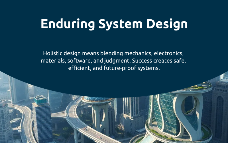
Designing Systems That Endure
Engineering design is more than a sequence of calculations or CAD drawings — it’s a holistic process that integrates mechanics, electronics, materials, software, and human judgment.
- Designing for systems requires balancing mechanical, electrical, fluid, and thermal considerations.
- Material selection must account for both performance and real-world failure modes.
- Manufacturing awareness ensures designs can be built reliably and economically.
- Simulation tools provide foresight but must be grounded in reality.
- Control systems and sensors form the intelligence layer of modern projects.
- Software integration defines scalability, security, and user experience.
For engineers and decision-makers alike, mistakes in any of these areas lead to cost overruns, delays, and failures. Success, on the other hand, creates products and infrastructure that are safe, efficient, and future-proof.
FAQ: Common Engineering Design Challenges
Q: What’s the biggest mistake engineers make when designing systems?
Failing to consider manufacturing and operational constraints early. A design that looks brilliant in CAD can be unbuildable, too costly, or prone to failure if real-world conditions aren’t factored in.
Q: How do I choose the right material for my design?
Balance mechanical properties, environmental conditions, manufacturability, and cost. Tools like Ashby charts and FEA can guide decisions, but real-world testing is crucial.
Q: What role does simulation play in modern engineering?
Simulation accelerates development and reduces costs, but it must be paired with engineering judgment. Models are only as accurate as the assumptions and boundary conditions applied.
Q: Why do prototypes sometimes fail even if simulations succeed?
Because simulations rarely capture all the messy realities of manufacturing variability, environmental conditions, or assembly errors. Prototypes are essential for bridging the gap between digital models and physical performance.
Q: How important is software in traditional mechanical or electrical projects?
Critical. Even purely mechanical systems increasingly rely on embedded software for monitoring, automation, and user interfaces. IoT integration adds complexity — and opportunity.